 This is my project of small 9- channel light controller. Basic requirements at the beginning was: it must occupy just one channel on receiver, must be small and must have bright intensity control for jets on my Su-27. The last development of RxE16 DLC ( DIY Light Controller ) is based on Waveshare RP2040 Zero board and uses JST 1.25mm connectors for LED connections.
I will add videos to explain principle of work, description etc. So this article will be consecutive upgraded.
Schematics & build data.
 Schematics in pdf can be downloaded here.
BOM is here.
Gerber files in ZIP are here.
3D views and layout.

PCB top view

PCB bottom view

Complete build top view.

LED connectors layout.

Servo cable input
3D printed files
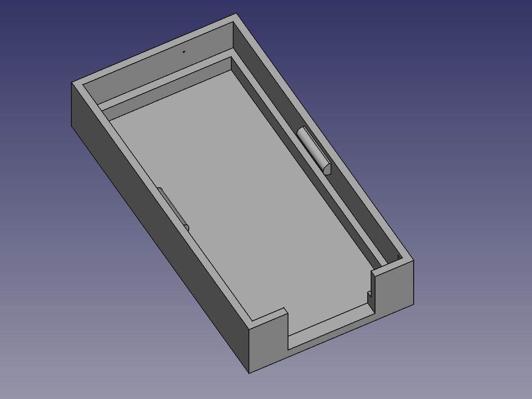
RxE16 3D printed case.
RxE16 spacer for RP2040 Zero board
3D files are here.
Explanation of principle – how does it work.
Examples and mixes used in videos can be downloaded here: Explanation_video_examples.
Installation on model
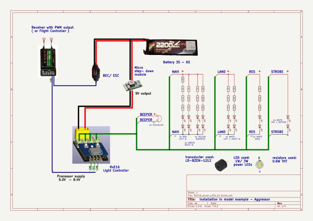
Schematics:
 RxE16 DLC is connected to receiver/ flight controller via a single servo cable. It requires special mix in TX, to control up to 9 channels.
RxE16 DLC has two power lines:
- processor supply line – servo cable from receiver/ flight controller, max. 8.4V
- LED power supply – from battery/ step- down module/ BEC, etc.
Both power lines share the same GND.
You can use any LED on LED channels that match Your requirements. Please note, that STROBE channel has built- in current limiter ( R4/ 1 ohm ), so You can use power LED without resistor in serial. Approx. values values for current limiter ( R4 ) : 1 ohm => 0.8A, 0.82 ohm => 1 A.
Please take care about power dissipation of LEDs and resistors!
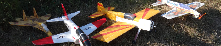
Installation example on Su-27
Here You can find as example my first DLC build ( use translator, it`s in Slovak ).
 Flying example:
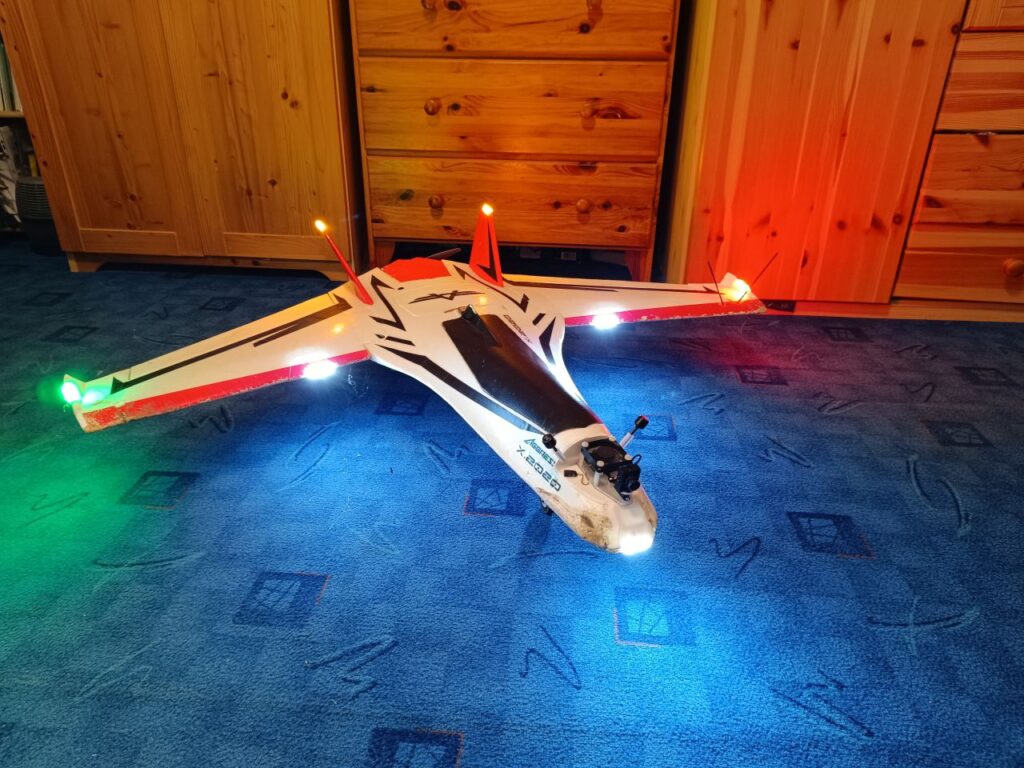
Installation example on Aggressor.
 Program files and upload.


Program files are here.
Program upload:
- connect RxE16 DLC with USB-C cable to Your computer
- press and hold BOOT button while short press RESET button
- RxE16 DLC will appear as new USB drive
- copy RxE11_v52_RP2040_Zero.ino.uf2 file there
Or compile RxE11_v52_RP2040_Zero.ino in Arduino IDE and upload from IDE.
Configuring/ calibrating.
- Connect RxE16 DLC via USB cable to computer and run any serial terminal ( Termite, Arduino IDE serial monitor … ).
- Use proper COM port.
- Type „help“, RxE16 DLC will send You list of commands.
- Calibrate RxE16 DLC via receiver or directly by typing of PWM pulse parametres.
How to calibrate RxE16 video:
Special mix in radio
Using RxE16 DLC require special mix in transmitter – that`s the reason of using OTX/ ETX radio. RxE16 DLC can operate in few modes ( Jet3, Jet1, Plane … ).
Mixes can be downloaded here: OTX-ETX-mixes
Default RxE16 DLC configuration is Jet3 mode, PWM pulse parameters 988us – 2012us.
Build pictures.


On- model installation example – Dolphine
Dolphine 845mm FPV Wing:


To be continued/ modified/ added YT videos…